• The development of any software program, including, but not limited to, training a machine learning or artificial intelligence (AI) system, is prohibited using the contents and materials on this website.

The Arduino Thread

bone

"bangle for president"
Joined
Jan 14, 2004
Messages
16,814
Location
belgium!!
Car(s)
Volvo V40 & Yamaha Banshee
everyone seems to be into lego, and i don't want to hijack that thread, but i was wondering if anyone here is also playing with arduino?
Arduino_Uno_-_R3.jpg


a while ago i bought a 4WD car frame to go loose on
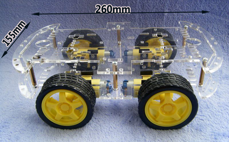
592530903_619.jpg

http://www.aliexpress.com/item/4WD-...coder-DC-for-Arduino-Robot-car/816849569.html

first we managed to get it running with a proximity sensor
mxSEOYVzRv6K7DqkL0Y4iLA.jpg

which basically fires a sound and counts how long it takes before it hears an echo to determine how far the object is, the goal was not to crash into things
which doesn't work that well, because the engines don't have a brake function, only forward, reverse and release. we're still to find a way to brake...
so it stops accelerating, and just rolls into whatever is in it's path :lol:

so we bought a gamepad!
Arduino-Esplora-348x196.jpg

http://www.extremetech.com/gaming/1...pad-makes-for-perfect-introduction-to-arduino
which, turns out, is intented to make your own gameboy or sth, not to remotely control something.

but after a lot of bickering and cursing, we managed to connect an nRF connector, so we now have radio communication between the remote and the arduino!
nrf24l01-300x186.jpg


but the car also has 4 wheels, so needs a big engineshield, meaning hardly any ports remain for communication.
so the car was equiped with a second arduino which is responsible for the communication with the remote, and just sends forward, reverse, left and right to the arduino controlling the engines.

and now we're in the process of creating a communication standard, so we can forward all actions on the gamepad to the arduino to the car. (which sounds easy enough, but drives me crazy :D)

if anyone else was thinking about getting one of those cars, don't get one with 4 wheels!!
you have no pins left on the arduine, it hardly turns, and since the engines aren't that high quality when driving forward it snakes from left to right...

also, the nRF connector is slooooooow, it's ok to make a POC, but not useable for something like this. if you just want to connect a light sensor or sth, it's fine, but not to control a moving object...
(still looking for an alternative)
 
Last edited:
it might...it might also fry the engines?
i'm afraid to test that :/
 
A really short burst? just enough to get the magnets engaged... I dunno, but I see your point.
Any forums on the maker's website or something, maybe someone came up with this problem and a solution.
 
When I raced slot cars, the brake function was applying up to half track voltage to the motor in reverse. So a blip of reverse should not hurt your toy in the slightest.
 
ok, will look into it! :)
thanks to the both of you!
 
While all your hardware hacking is pretty impressive, I'm left wondering if you're basically just building an remote controlled car?
 
wonder no more, that exactly what we did :)

it's hard to find a usefull project to built, whatever you're thinking of building, someone made a commercial version for next to no money, so if originality is a criteria before starting something, everything just stays in the box...it's the path to the result that's interesting, not the result itself ;)
 
I am using an arduino for Lucille's fuel injection project: Jumpered into what is called "tri-state mode" it takes a serial input signal and hands it over to my (emulated) Windows on a simulated RS232 port, thus saving me from buying one of these overpriced ALDL cables that, in fact, are only serial-to-USB-converters as well.

- - - Updated - - -

wonder no more, that exactly what we did :)

it's hard to find a usefull project to built, whatever you're thinking of building, someone made a commercial version for next to no money, so if originality is a criteria before starting something, everything just stays in the box...it's the path to the result that's interesting, not the result itself ;)
That's the spirit.

Useful-yet-useless projects my buddy Paul has built include a randomized, fading "glow" effect for the cigarette in the mouth of an Elvis statue and a "shotglass curling" (which, as it sounds, means playing curling with empty shotglasses on a bar) scoring machine.
 
I made a little box to control the anti fog mirror in our bathroom.

It has a cheap arduino nano clone I got from china for about ?7, a humidity sensor, a light sensor, a relay and an old usb PSU.

I also hacked up the code I found for the humidity and light sensor so that it only turns the mirror on if the light is on and the RH is over 40%.

When the light goes off, or RH goes below 40% the mirror turns off.

My problem is that the mirror is too slow to bother with, it wasn?t a good buy, it takes so much time to heat up, that you can have a shower, get dry and be on the way to work before the thing is suficiently clear to be useful.

It was a fun little project though.
 
Last edited:
Cheap shaving cream(real cheap) rubbed on a clean mirror and then wiped down will improve that a bit.
 
a "shotglass curling" (which, as it sounds, means playing curling with empty shotglasses on a bar) scoring machine.

lol! that intrigues me! :D
how do you play it? (and how happy does it make the barkeeper? :D)
 
My practical knowledge in this area is limited to basic home electrics, some CNC programming, some PLC, and hitting things with a hammer, so how much expertise does one need to get started with this sort of thing? Does a starterkit come with an idiots guide or do you need pre-existing knowledge?
 
Last edited:
the basis realy is for dummies, very simple, intuitive tutorials etc, and the board is made with novices in mind, very sturdy and protected, i've fucked up a lot, but never harmed the board...

being able to read code helps, so you know what to copy-paste :p, but the programming is in C, which isn't that hard once you get the basics...
but my biggest problem is that i have hardly any knowledge about electronics. once you go away from the tutorial, you have to figure out yourself what resistors to use and how to wire everything...
bachelor in IT, yet never ever during school we were ever introduced to that, which is a big shame if you ask me, should be part of the education of an ITer!

i downloaded an app called electroDroid, and that's a big help!
 
Last edited:

View: https://media.giphy.com/media/Xa4lNyu3RSw6hHadLM/giphy.gif

I thought about creating a new thread instead of clogging up New Toys or losing things in Random Thoughts, but apparently this exists so I'll just shovel off the top surface of soil and carry on with it.

I'll probably re-post my old projects in here so they're together but for the time being I'll just be looking at the new project, adding a charge complete tune to my power tool battery charger(s). As we were discussing in the New Toys thread, the standard 18V Makita charger can play a range of tunes when charging is complete but they're all very annoying. My Milwaukee M12 charger doesn't make any noise when charge is complete, so why not add the feature to both with an Arduino?

I already have some Pro Micro Arduino Leonardo clones, a box of opto-isolators, a piezo buzzer and a couple of 3.5mm TRS sockets. Instead of trying to build it in to one of the chargers it would be better as a standalone device, making it easier to power from USB. I would need three wires from the Makita charger (a positive for each opto-isolated LED and a common ground) and two wires for the Milwaukee charger (just positive and ground for the green light as it only ever illuminates when charging is complete). These would only be carrying tiny signal currents so 3.5mm audio cable will be fine.

I've found that Arduinos can apparently play tunes on a piezo speaker right out of the gate, assuming the tune fits in memory, and there's a site that offers to convert MIDI to the code required. I can breadboard the whole thing straight away, using a 3V supply and buttons/jumpers to simulate the charger activating the LEDs.
 
Could another solution be to monitor the charger's power draw, and when it drops below a certain threshold, you know it's effectively done charging? Could the alarm then get it's power from the same power pass-through that's reading the power draw?
 
Could another solution be to monitor the charger's power draw, and when it drops below a certain threshold, you know it's effectively done charging? Could the alarm then get it's power from the same power pass-through that's reading the power draw?
It could be, that's a little bit more complicated than my solution though and I've already done it. :p

I now have 4 tunes that I can play and a breadboard setup to mimic the lights. It uses a single variable in the code, set to 0 at start up. If the red light is on the code then looks for a green light, setting the variable to 1 if the green light is on. A second part of the code checks for that variable and looks for the red light to be off, which if it is will trigger the tune and then set the variable back to 0.

The only time these events occur is as the battery begins to charge, nears completion and then ends. Sitting idle won't trigger it and it won't re-trigger once the variable is reset.

Code:
void loop() {
  if (digitalRead(5) == 0)
  {
  // Red light is on
    if (digitalRead(6) == 0)
    {
    // Green light is on with red, set variable to 1
    trigger = 1;
    }
  }

  if (trigger == 1)
  //Check for red light going off
      if (digitalRead(5) == 1)
    {
    // Red light off, play music and reset trigger to 0
    trigger = 0;
    midi();
    }
}

For the digital reads in this code, 0 indicates a closed circuit as the pin is pulled high during the setup. The midi section is separate and is a load of tones in sequence.

This is the complicated one for the Makita charger, the code for the Milwaukee one just needs to sniff the bloody green light.
 
Quick picture of the breadboard to replicate the charger lights:


Hold the button on the left, then hold both and let go of the left to replicate the sequence. Top cables go off to the Arduino, two positives coming from pins 5 & 6 and a shared ground. Opto-isolators bridge the two sides of the breadboard.
 
Top